The ESP8266 lacks any hardware support for PWM. Any ATtiny, PIC or any ARM Cortex M0 based SoC fares better in this regard, although the smallest SoCs may have only one or two channels.
As an alternative to hardware PWM it is possible to do PWM purely in software, typically assisted by interrupts from a hardware counter. For the ESP8266 a software PWM implementation is available in the SDK provided by Espressif, but it comes with several strings attached:
- It has a quite awkward API, the documentation lacks several important points open
- As any interrupt based implementation it is susceptible for glitches
- The duty cycle is limited to 90% maximum
The missing manual parts
The API has four important functions to control the PWM, as follows:
void pwm_set_duty(uint32 duty, uint8 channel)
Set the duty for a logical channel. One duty unit corresponds to 40ns. The maximum should be period / 40ns, but due to the implementation there is a fixed dead time of 100μs which limits the maximum duty to 90% when using a period of 1ms (i.e. a frequency of 1kHz).
void pwm_set_period(uint32 period)
Set the PWM period to period microseconds.
void pwm_start(void)
Needs to be called before any pwm_set_duty, pwm_set_period calls take any effect. Does some preparatory work needed for the interupts handler to do its job of toggling the GPIOs.
void pwm_init(uint32 period, uint32 *duty,

uint32 pwm_channel_num, uint32 (*pin_info_list)[3])
duty points to an array of duty cycles, the number of array elements depends on the number of used channels. From the documentation it is not obvious if this is only needed for initial settings, if this is also accessed after the pwm_init call (e.g. ownership of the array is transfered) and if is save to pass NULL here.
pin_info_list points to an array of arrays. It better had been declared as an array of structs, each struct storing the configuration of a GPIO pin. As is, each 3-tuple stores:
- the name of the MUX configuration register as documented in the GPIO chapter of the SDK, see the PIN_FUNC_SELECT macro
- the name of the MUX setting, see GPIO SDK documentation
- the number of the GPIO from 0 to 15
One 3-tuple is needed for each PWM channel/GPIO pin. Ownership transfer is not documented.
The „90% maximum duty“ limitation
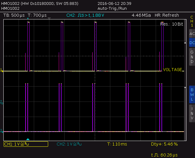
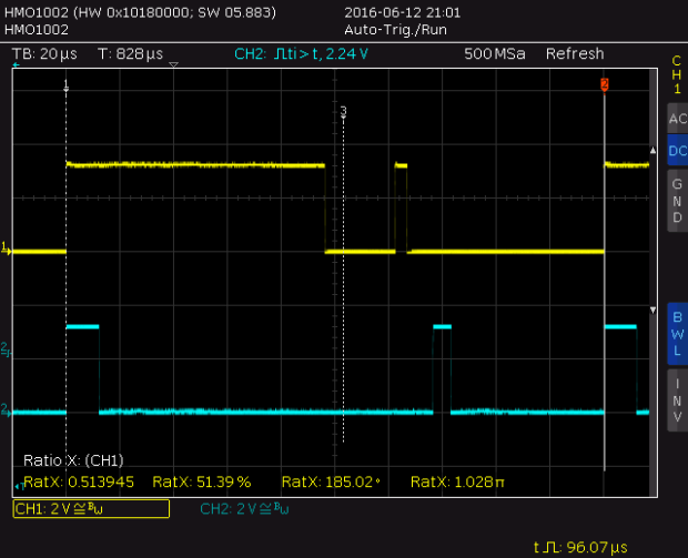
The maximum duty limit is an implementation artifact. To understand where this limitation is coming from, it is necessary how the the software PWM works. The following two scope traces both show the same signals, 2 PWM channels with a duty of 1467 (58.7μs) and 399 counts (15.9μs), with a specified period of 1000μs, but different timebases (500μs/div resp. 20μs/div).

1kHz PWM from Espressif SDK. A specified period of 1 milliseconds results in a period of 1.1 milliseconds.
As can be seen, in each period typically two pulses are generated, a short and a long one. To calculate the length of the pulses, divide the duty count by (400/3). The integral part is the length of the longer pulse in units of 5.32μs, the remainder is the length of the short pulse. For the given traces:
PWM channel 1
long: [1467 × 3 / 400] × 5.32μs = 11 × 5.32μs = 58.52μs
short: (1467 – 11 × 400 / 3) × 40ns = (1467 – 1466) × 40ns = 40ns
PWM channel 2
long: [399 × 3 / 400] × 5.32μs = 2 × 5.32μs = 10.64μs
short: (399 – 2 × 400 / 3) × 40ns = (399 – 266) × 40ns = 5.32μs
From the first trace one can also see that the long pulses run in parallel during the set period of 1000μs, but the short pulses are generated in a fixed size timeslot of 100μs sequentially, i.e. the actual period is 1100μs. Thus the maximum duty cycle is 1000μs (long pulse) + 5.32μs (short pulse) / 1100μs = 91.4%.
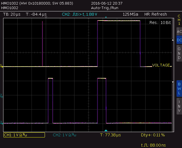
For higher PWM frequencies this can be a real problem. When the period is set to 100μs, e.g. 10kHz, the PWM actually runs with 5kHz and the duty cycle is limited to ~50% (Channel 1):

10kHz PWM from Espressif SDK. The PWM actually runs at 5kHz, as the right half is not accounted for.
A PWM from scratch
For the reasons stated above, I thought about a new PWM implementation. Requirements were:
- Opensource, to be hackable
- Usable for 1 to 8 PWM channels
- Full 0% to 100% duty cycle
- Drop-in replacement for SDK PWM
First thing I learned during the implementation is the quite high interrupt overhead of the NON-OS SDK (same may apply for the xtensa FreeRTOS port) [1]. The interrupt handler which has to be provided to the SDK interrupt attach function is just a normal function (ABI wise), while the lowlevel interupt handler doing the housekeeping, like register saving and dispatching, is hidden somewhere in the ROM. This housekeeping adds about 2.5μs of overhead, which limits the maximum rate for doing timer based interrupts to about 3μs.
So to get a resolution better than 3μs at least part of the GPIO pin toggling has to done with busy loops inbetween. While busy waiting is normally frowned upon, in this case is no worse than interrupts – either way the CPU is busy, either by spinning or by completing the interrupt handler.
Another limiting factor is the access time of the ESP8266 peripheral registers. As others have noted, a write to these registers take about 6 CPU cycles, i.e. 75ns.
Design choices
- Mixed interrupt/busy loop concept with single pulse per period
- Base interval of 200ns
- Phase mirroring for duty cycles above 50%
The third point is the most important one, the one that needs some explanation. A software driven PWM typically enables all active channels at the beginning of the period (t=0) and then one after the other switches the channels off again, depending on the respective pulse width.
For channels with a duty cycle above 50%, these can also be interpreted as having a duty cycle of 100% – duty, but an inverted
polarity. This interpretation allows to remove any switching from the second half of the period, and in turn enables using this timeframe for a more fine granular pulse width generation.
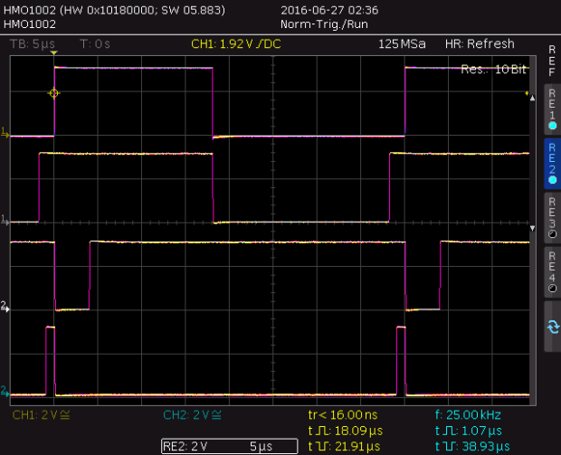
So, how does it look like? Here are 4 PWM chanels, 25kHz PWM period, duty cycle of 45%, 50%, 90% and 2.5% from top to bottom:

25kHz PWM from new implemantation
Implementation details
The important parts are the actual interrupt handler and the setup routine for the PWM control. Both deal with an array of sequential PWM phases. Each phase switches some GPIOs on and off, and then delays execution until the next phase starts:
struct pwm_phase {

int32_t ticks;

uint16_t on_mask;

uint16_t off_mask;

}
For the 4 channel PWM above, there are 5 phases.
- T= 0us: Enable channel 1, disable channel 3 and 4
- T= 4us: Enable channel 3
- T=18us: Disable channel 1 and 2
- T=38us: Enable channel 2
- T=39us: Enable channel 4
After the first three phases, the timer interrupt is set up for the delay, the last two phases are done with busy waiting inbetween.
The heavy lifting is done in the setup routine called by pwm_start. It sorts channels by duty cycle, aligns PWM pulses to satisfy interrupt rate constraints (as done for channel 1 and 2 here) and transforms the absolut switching times to delays.
The interrupt handler is designed to be as lightweight as possible – it has to be able to switch arbitrary GPIOs every 200ns. To reach this goal, it uses several tricks to minimize instruction count:
- Use a struct for related data. This allows the compiler to use relative load with a single base offset for multiple variables.
- Use a struct for the GPIO and timer registers. The SDK defines these as independent memory offsets, again combining these into a struct allows to use relative stores.
- Do not use the SDK GPIO manipulation macros. These insert a „memw“ (memory wait) instruction, costing two extra cycles (thats 25 precious nanoseconds out of 200 available).
But enough words, code is available here:

This is great work, indeed. I may use this improved PWM driver to control some water valve servos in my project. I’ll let you know the results. Thanks!
It’s a great work, for sure.
I was reading your example but, I was wondering it could be possible to include GPIO4 and GPIO5(this already in your example) in order to use the ESP12 shield motor board, which uses arduino pins 2 and 1 to drive motors PWMs.
Thanks for your work !!
You can use any of the GPIOs 0 to 15, you just have to set the pin function correctly. Pin function registers are:
GPIO0: PERIPHS_IO_MUX_GPIO0_U
GPIO1: PERIPHS_IO_MUX_U0TXD_U
GPIO2: PERIPHS_IO_MUX_GPIO2_U
GPIO3: PERIPHS_IO_MUX_U0RXD_U
GPIO4: PERIPHS_IO_MUX_GPIO4_U
GPIO5: PERIPHS_IO_MUX_GPIO5_U
GPIO6: PERIPHS_IO_MUX_SD_CLK_U
GPIO7: PERIPHS_IO_MUX_SD_DATA0_U
GPIO8: PERIPHS_IO_MUX_SD_DATA1_U
GPIO9: PERIPHS_IO_MUX_SD_DATA2_U
GPIO10: PERIPHS_IO_MUX_SD_DATA3_U
GPIO11: PERIPHS_IO_MUX_SD_CMD_U
GPIO12: PERIPHS_IO_MUX_MTDI_U
GPIO13: PERIPHS_IO_MUX_MTCK_U
GPIO14: PERIPHS_IO_MUX_MTMS_U
GPIO15: PERIPHS_IO_MUX_MTDO_U
You can use up to 16 PWM channels, if you want to use more than 8, redefine MAX_PWM_CHANNELS to the appropriate value.
Thanks once more!!!