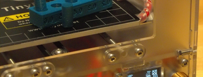
As long as one sticks to printing PLA, a printer without heatbed is ok, but for ABS or PETG a heatbed is a must.
The TinyBoy2 bed is actually a heatbed, although the wiring is missing, and a thermistor is required as well. The SMELZI controller board has a PWM controlled MOSFET, which is connected to the „HOT-BED“ socket, so making the bed a heatbed is straightforward.
Required Tools:
- Soldering Iron (80W minimum)
- Hex screwdriver
- 2.5 mm Drill
- File or handheld milling machine (Dremel) or …
PARTS:
- 100k SMD thermistor (size 0805, or 1206)
- pair of thick wires (35 cm) for the heater
- pair of thin wires for the thermistor
- 2,54 mm 1×2 connector (e.g. Dupont connector)
- M3x6 screw
- thin sheet of plastic, ~10×30 mm
1. Adding the thermistor

Added SMD thermistor, 1206 is slightly to large for a 0805 footprint …
2. Soldering the wires to the bed
As the bed is aluminium, soldering anything to it can be tricky, and you need a powerful soldering iron to get the solder to temperature. I ended up using two soldering irons simultaneously, one on each end of the solder blob.
The two wires for the heater go to the larger pads, the thermistor sensing cable has to be connected to the smaller pads. As we are connecting resistors here, direction does not matter.
3. Creating a strain relief for the wires
The wires will be bent all the time while the bed moves in the Y direction, so we need a strain relief or the cables will break after short time of operation.
I drilled a 2.5 mm hole into the red bed bracket/slide and pushed a M3 screw into it. The strain relief is created from a small sheet of plastic, size 10×30. Pick 3 small holes into the plastic, at 5, 15 and 25 mm from the edge. Wrap it around the cables, the holes should line up. After assembling, it should look similar to this:

Heater cables (red), temperature sensing cables (striped)
It is important the cables do not extend beyond the edge of the slide, otherwise the cables will colide with the case.
4. Creating a duct from the top to the bottom
I chose to exend the hole for the extruder stepper, which allows the cable to move freely when the board moves:
Remove the extruder before creating the hole, its just 4 screws and will simplify working in the constrained space a lot!


